
Graph Layout with Spring Embedders in F#
05 Apr 2021I have been obsessing over the problem of graphs layouts lately. To provide a bit of context, the starting point for that obsession was role-playing games. When running an adventure, you often need to quickly find various pieces of information, and how they are connected, for instance “Who is the leader of the Lampblacks”, or “What are notable locations in the Six Towers district”. This type of information clearly forms a graph. It would be nice to be able to navigate that information quickly, to figure out how various entities are connected.
This is how I got interested in building up a knowledge base for a game I am running (the wonderful Blades in the Dark), and displaying the information as a graph.
Before diving into the code, as a teaser, here is how the result looks like at the moment:
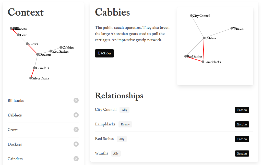
Or you can try it live here.
I can search for entries, select them, and as I do, the relationships between them is added to the graph, automatically highlighting existing connections.
Graph Layout with Spring Embedders
The part I found interesting was the automatic graph layout. The goal here is to take a graph, a set of nodes (or vertices) which may or may not have edges connecting them, and display them in a manner that is hopefully informative and pleasing to the eye.
As it turns out, this is not an entirely trivial problem.
What we want is a representation where:
- entities that are connected appear close to each other,
- nodes are nicely spread out.
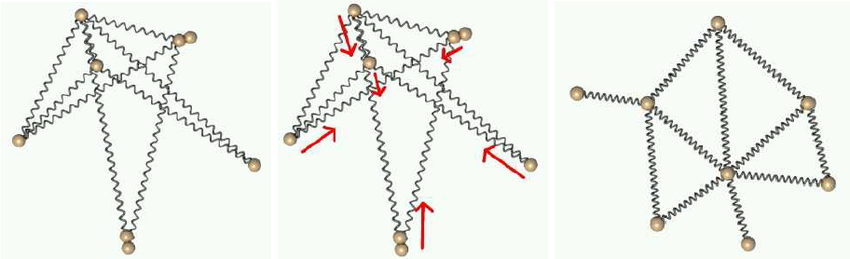
A classic technique to solve this problem is called spring embedders. If you want a great and fairly accessible overview of the topic, I recommend reading “Spring Embedders and Force Directed Graph Drawing Algorithms”, by Stephen G. Kobourov. In a nutshell, the idea is to add physical forces such as springs between connected nodes, to represent the tensions that exist in the network, and let them play out until the system reaches some equilibrium.
The chart below, taken from the same article mentioned above, illustrates the idea. We place the nodes randomly on the chart, and add springs between the nodes that are connected. Springs will pull together nodes that are too far apart, and push away nodes that are too close to each other. If we let the springs progressively adjust, we should end up with a balanced layout like this one:
The algorithm I ended up using is the second one in the article, the Fruchterman-Reingold algorithm, with a slight modification (more on this later). In this version, instead of springs, the 2 forces at play in the graph are:
- a repulsion force, which pushes every pair of nodes away from each other, and gets weaker as nodes get further apart from each other,
- an attraction force between connected nodes, similar to an elastic band, pulling them towards each other.
I implemented the SPRING algorithm as well (the first one presented in the article), but I got better results with Fruchterman-Reingold, which I will focus on here. You can find the full implementation in the Calder repository.
Implementation: Forces
At the heart of the algorithm, we have nodes that are located in a certain position, and forces that apply to them, pushing or pulling them into a direction. Let’s start by modelling that.
We can represent a position by coordinates X and Y, like this:
type Point = {
    X: float
    Y: float
    }
Similarly, we can represent a direction by the differences in the X and Y positions, DX and DY, like this:
type Direction = {
    DX: float
    DY: float
    }
In our model, a node at some Point will be subjected to multiple forces, each described by a Direction. We would like to be able to easily add them together, and perhaps perform some operations like multiplying a Direction by a number. Let’s expand a bit our Direction type to do that:
type Direction = {
    DX: float
    DY: float
    }
    with
    static member (*) (scalar: float, direction: Direction) =
        {
            DX = scalar * direction.DX
            DY = scalar * direction.DY
        }
    static member (+) (dir1: Direction, dir2: Direction) =
        {
            DX = dir1.DX + dir2.DX
            DY = dir1.DY + dir2.DY
        }
    static member Zero = { DX = 0.0; DY = 0.0 }
    member this.Length =
        pown this.DX 2 + pown this.DY 2
        |> sqrt
Thanks to the infix operators, we can now do things like this:
let dir1 = { DX = 0.0; DY = 1.0 }
let dir2 = { DX = 1.0; DY = -2.0 }
let total = dir1 + 2.0 * dir2
total.Length // float = 3.605551275
We added the Zero property, so we can safely do things like summing up list of directions, and gracefully handle the case of an empty list.
In a similar fashion, we can expand Point a little like this:
type Point = {
    X: float
    Y: float
    }
    with
    static member (+) (pt: Point, direction: Direction) =
        { X = pt.X + direction.DX; Y = pt.Y + direction.DY }
    static member (-) (pt1: Point, pt2: Point) =
        { DX = pt2.X - pt1.X; DY = pt2.Y - pt1.Y }
What does this buy us? First, we can now add a Direction to a Point, and get the position of the resulting Point. Then, we can substract 2 points, giving us the direction between them.
With this out of the way, we can now starting to play with forces. I ended up representing a Force as an interface, with a single method, applyFrom:
type Force =
    abstract member applyFrom: origin: Point -> target: Point -> Direction
The idea here is that I want to apply a force to a Point, the target, from a particular origin, another Point. The result should be a Direction, describing where that force pushes or pulls, and how strongly (the length of the direction).
Let’s apply this to the Fruchterman-Reingold algorithm. Two nodes that are connected attract each other, by a force fa(d) = d^2, proportional to the square of their distance d. That is easy enough to implement, using object expressions:
let attraction = {
    new Force with
        member this.applyFrom origin target =
            let direction = target - origin
            let length = direction.Length
            let strength = (pown length 2)
            strength * direction
    }
Let’s illustrate on a simple example, where p1 and p2 are two connected nodes:
let p1 = { X = 0.0; Y = 0.0 }
let p2 = { X = 1.0; Y = 2.0 }

p1 |> attraction.applyFrom p2
… which gives us:
val it : Direction = { DX = 5.0; DY = 10.0 }
Similarly, from p2:
p2 |> attraction.applyFrom p1
… we get
val it : Direction = { DX = -5.0; DY = -10.0 }
In other words, p1 and p2 exert opposite but equal forces on each other, pulling the nodes towards each other. The repulsion force is quite similar, so we won’t go into further details. You can find the corresponding code in the Auto.fs file.
Implementation: Graph and Layout
Now that we have a model for the physics of forces, we need a graph to apply them to. I ended up separating things into 3 parts:
- a
Graphis simply a collection of nodes and edges, - a
ForceGraphis a graph where each node and edges has forces attached, - a
Layoutis the current position of every node of aGraph.
The Graph type is pretty straightforward, it is a set of nodes (of generic type 'Node), and edges:
type Graph<'Node when 'Node: comparison> = {
    Nodes: Set<'Node>
    Edges: Set<Edge<'Node>>
    }
    with
    static member empty<'Node> () =
        { Nodes = Set.empty<'Node>; Edges = Set.empty<Edge<'Node>> }
    static member addNode (node: 'Node) (graph: Graph<'Node>) =
        { graph with Nodes = graph.Nodes |> Set.add node }
    static member addEdge (node1: 'Node, node2: 'Node) (graph: Graph<'Node>) =
        let edge = Edge.create(node1, node2)
        { graph with Edges = graph.Edges |> Set.add edge }
I went back and forth with Edges, and landed on this:
type Edge<'Node when 'Node: comparison> =
    private | Edge of 'Node * 'Node
    with
    static member create (node1: 'Node, node2: 'Node) =
        if node1 < node2
        then Edge (node1, node2)
        else Edge (node2, node1)
    member this.Node1 = match this with | Edge (node1, _) -> node1
    member this.Node2 = match this with | Edge (_, node2) -> node2
The issue I was trying to avoid here is that an edge between Node1 and Node2 is the same as the edge between Node2 and Node1 (we assume an undirected graph here). Representing an Edge as, for instance, a record with 2 nodes would force us to check both possible positions of the nodes to see if 2 edges are equal. Here, we hide the internals of the Edge, and guarantee that 2 nodes will always be stored in the same position: the only way to instantiate an edge is by calling the factory method create, where we ensure they are ordered consistently:
let edge1 = Edge.create (1, 2)
let edge2 = Edge.create (2, 1)
edge1 = edge2 // true
The ForceGraph type is simply an extension of this, reorganizing the information so we can quickly retrieve all the forces that apply on a particular node:
type ForceGraph<'Node when 'Node: comparison> = {
    Nodes: Map<'Node, Force>
    Edges: Map<'Node, Map<'Node, Force>>
    }
Each node has a force attached (presumably a repulsion force). Edges are re-organized in terms of nodes: we store the force exerted by an edge as 2 separate forces, representing the force a node receives from the other end of the edge.
And that’s pretty much it. With that in hand, we can now define a Layout like this:
type Layout<'Node when 'Node: comparison> =
    {
        Nodes: Map<'Node, Point>
    }
… and compute, for a particular Layout, what force applies to a node:
let nodeForce (graph: ForceGraph<_>) layout node =

    let position = layout.Nodes.[node]

    let nodesRepulsion =
        graph.Nodes
        |> Seq.sumBy (fun kv ->
            let force =
                if kv.Key = node
                then Neutral
                else
                    kv.Value
            position
            |> force.applyFrom (layout.Nodes.[kv.Key])
            )

    let edgesAttraction =
        graph.Edges
        |> Map.find node
        |> Seq.sumBy (fun kv ->
            let force = kv.Value
            let origin = layout.Nodes.[kv.Key]
            position
            |> force.applyFrom origin
            )

    nodesRepulsion + edgesAttraction
We compute the attraction exerted by every node in the graph, sum these all together, and do the same for every edge, and… we are done. Given a specific Graph and Layout, we can compute what force applies to each node, and update their position, following one of the algorithms described in the paper.
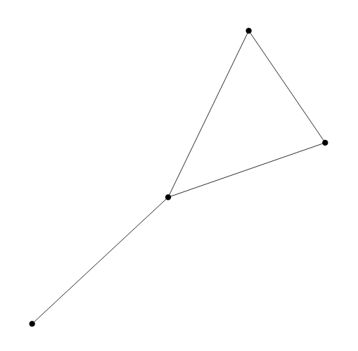
In its simplest form, you can use Calder like this:
// create the graph
Graph.empty ()
|> Graph.addNode 1
|> Graph.addNode 2
|> Graph.addNode 3
|> Graph.addNode 4
|> Graph.addEdge (1, 2)
|> Graph.addEdge (1, 3)
|> Graph.addEdge (1, 4)
|> Graph.addEdge (2, 3)
// and solve it using defaults
|> Auto.solve
… which will create the following layout:
Parting Thoughts
I’ll leave it at that for today, with two parting comments.
First, if you look at the implementation of ForceGraph, you will see that it is slightly different from what I presented above, with an additional field, Center:
type ForceGraph<'Node when 'Node: comparison> = {
    Nodes: Map<'Node, Force>
    Edges: Map<'Node, Map<'Node, Force>>
    Center: Option<Force>
    }
What is that about? The short version of it is, I realized at some point that the Fruchterman-Reingold layout algorithm was producing pretty bad results when the graph was disjoint (that is, some sub-graphs had no connections to others). It makes total sense given the algorithm: a node without any connection will be pushed away without any attraction force keeping it close to the rest. To address that issue, I ended up adding an (optional) central force, which pulls all nodes towards the center of gravity of the layout.
The second comment is that I keep being impressed by Fable. I am very incompetent in all things web related, and was expecting my code to perhaps cause issues when used in a Fable Elmish app. Turns out, everything worked just as advertised. My F# code compiled without complaints, and… I was surprised at how fast everything ran.
Anyways, that’s it for today, hope you found something of interest in this post! The whole code is on github in case you are curious, and… let me know if you have questions or comments, and stay safe out there!